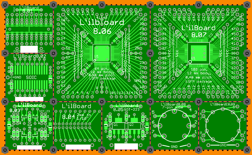
All board designs so far.
The Power Supply Boards:
Two linear regulators (positive and negative); two switching regulators (buck and boost); two battery/cell holders (the 9 V holder has a rail splitter option); a wall wart jack (which can handle 5 sizes of plug) and a bridge rectifier board comprise the Power Supply line-up.
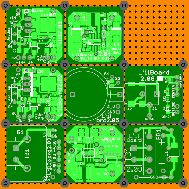
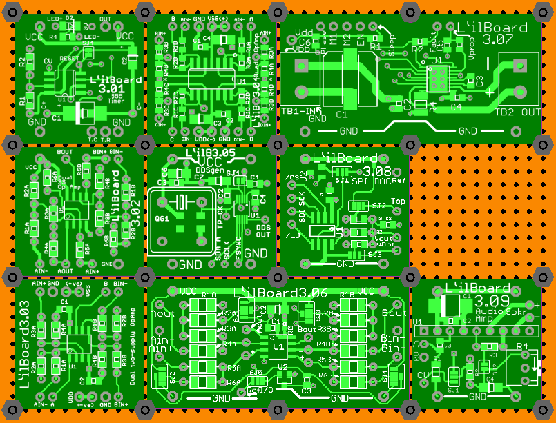
The “Analog” Boards:
Four different op-amp boards; a 555 timer board; a DDS board; a motor driver; an SPI DAC and an audio amplifier.
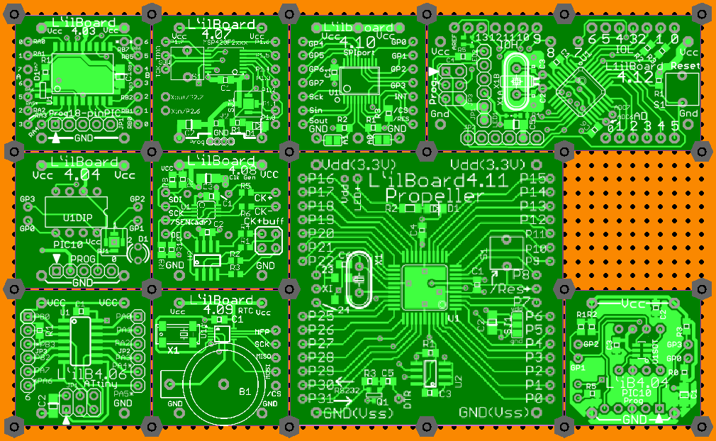
The “Digital” Boards:
6 processor boards; a real-time clock board; an SPI-controlled clock generator; an SPI port expander.
The “Human Interface” Boards:
A 4-button/4-LED board; an 8-LED board; a DIP or rotary switch board; a power switch, a DPDT switch and two boards which are arguably not in the right category: a dual power FET, and a dual digital potentiometer board.
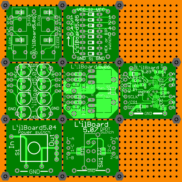
The “Interface” Boards:
USB peripheral (RS-232 plus); USB host (Vinculum); RS-232, RS-485 and LVDS transceivers; SPI to Ethernet; micro and normal SD jacks.
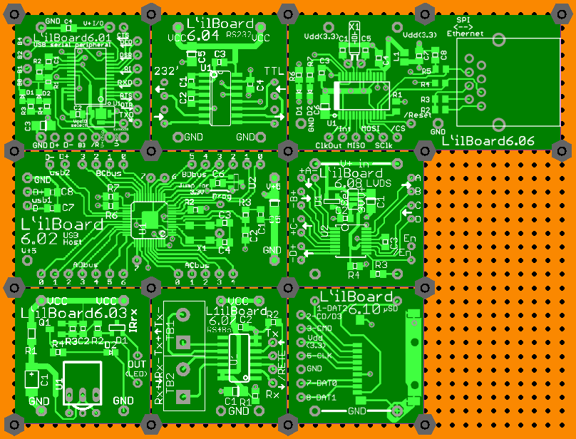
The “Connector” Boards:
One of the most useful ones, in that it has been used in almost all tessellations that I have done so far, is the 4-way terminal board; two RJ-style connectors; several video (S, VGA, {DVI} and {HDMI}); USB connectors; a PS/2 jack and a DE-9 connector.

The Uncommitted Boards:
A variety of patterns for many package styles. Some, like the 8.02, have different patterns top and bottom as seen in the second image.
