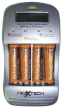
The saga of a failed consumer product...neXXtech model number 2300451 battery charger.
What is this page about?

I started this because I had bought a 4-cell charger that had a problem, one that turned out to be easy to fix. So, to try and prevent some of the same chargers ending up in the landfills of North America, I thought I'd describe the simple repair. Then another problem appeared, then another, then, another! The problems all have a common cause: the mechanical aspects of the design were neglected, however, they were all easy to find and fix. In one case the designers decided to complete circuits by soldering tracks together where one board plugged into another by means of tabs plugged into slots. Two of the other problems were caused by a different lack of consideration of the mechanical design: the input power jack is stressed when the power plug is inserted or removed, causing tracks to break. I still think the electronic design is more than adequate, and the unit's firmware seems up to the task too. Perhaps this page will serve as a reminder of what not to do for some future commercial product designer!
First problem...dissappearing charge sites...
I bought one of these chargers in 2006 just before a trip. It seemed like a pretty good deal since I needed some cells as well (it came with 4 each, high capacity AA and AAA rechargeable Ni-MH cells). Since I bought it the day before the trip, I couldn't return it when I found out that it didn't work so well: when I tried it at first, one, then two of the charging sites were not working (no indication that a cell was present, so no charging took place in the affected sites). Eventually, after another half a year or so the other two charging sites died as well. Totally gone! Since I'm always interested in how such things are put together, I took it apart. The product description, which was at “The Source by Circuit City's” here (gone by November 2009) had a few product reviews, several describing familiar problems.
Taking it apart...
Two small Phillips head screws are all that fasten the back on. Once they are out, there are two locking tabs to release. These are at the sides near the bottom. That's all.
Four small Phllips screws hold the main board in. If you don't need to, don't remove these! I took the board out, but if the symptoms that your unit has are the same as the ones mine had, you don't need to do that. The board is tricky to get back in since the spring-loaded terminals have to be compressed just so to do this. (I used some tape and some AWG #30 wire-wrap wire to hold the terminals in during re-assembly.)
Finding the problem...
First, some reverse Engineering. There are three PCBs in the design. Only the small one which connects the positive sides of the cells to be charged is double sided. The main PCB contains a µController, power supplies, two charging control switches, and the LED drivers to control whether each LED is red or green or yellow (both red and green on).
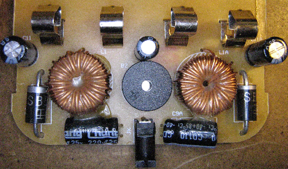
The unit has two obvious switching (buck configuration) power supplies, at the bottom left and bottom right of the main board (where bottom is the input connector end). The measured output voltages of both of these were 2.17 V when I measured them—presumably they can be different voltages depending on whether AAA or AA cells are being charged. Each regulator supplies a pair of cell sites: each site in the pair must have the same size cell. The inductors and catch diodes for both of these are on the other side of the board, Photo 1. I can't find the data for the switch-mode controller ICs (their markings are something like “PT4053” or perhaps that is “RT4053”), however the power FETs are clear: Q15 and Q15A are “APM9435” devices—a search turns up a data sheet for a 30 V, 4.6 A P-Channel MOSFET.

Photo 1. On the bottom side of the board we find the larger switching regulator components: input and output filter capacitors, the negative cell terminals, the 3 V supply filter cap, the power input jack, and the buzzer.
As well, the µController (a Samsung S3C9228 in a 44-QFP) gets 3 V. It seems that IC1 is a 3.0 V regulator, its pinouts are consistent with at least some 3.0 V LDO regulators in the SOT-23 package. Not sure what Q14 is, though: it seems to control the power to, or perhaps drop some power before, IC1...
To the left of the µController there is a set of components, R13 through R20 and D1/C1 through D4/C4, dedicated to conditioning the cell voltages so that the controller can read them (pins 1 through 4 of the chip are ADC channel inputs). Once this was figured out, it became clear that the cell voltages were not being seen by the controller.

Photo 2. The tabs of the cell-positive PCB which come through the main board and connect to the main board via solder bridges.
The four traces which connect the battery-positive board to the main board (the arrow in Photo 2) were the culprits. These feed back the cell voltages to the Controller, but each and every one of them was open! It seems that a board mounted at right angles, slotted through another board and with traces soldered to each other is an unreliable means of connection! Since I did not remove the board I have no way of knowing whether the slot has plating inside it for each conductor, but as far as I know this is not done.
There may be another factor here: the instructions clearly state: “7. Remove batteries from the charger if it's not being used for long periods of time,” yet the unit came with the AA cells installed in the charging slots. I suspect that continued stress from the cell contact springs combined with vibration during shipping could have easily cracked the culprit solder connections.
The simple fix...
Once the problem was identified, it was a simple matter to re-melt the solder at each connection (Photo 2). This fixed the problem, however if it recurs, I would solder in jumpers to bypass these problem connections. Update: more than 5 years later it is still charging at all sites just fine.
The second problem...nothing doing!...
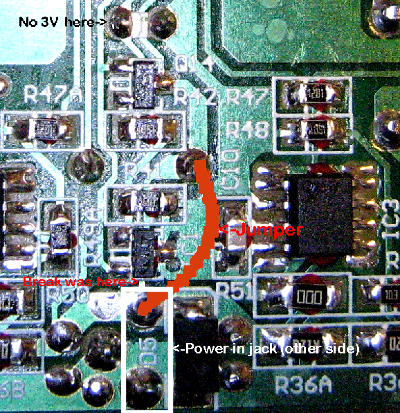
After a few months of perfect operation, one day the unit failed to start up. Luckily I still had the notes from the first time, so it was a fairly quick diagnosis: the 3.0 V was missing (Vdd to the µController), and it seemed that this was due to the fact that the 12 V input was not getting to Q14 (or IC1 via Q14). I traced this down to a cracked trace just below IC1. Instead of trying to solder so near IC1, I installed a jumper from the positive pin of the input connector to the Positive supply pad (through-hole) of the Buzzer. See Photo 3.

Photo 3. The missing 3 V supply fix.
This fixed the second problem. I expect that the source of the problem is mechanical, in that leverage of the power plug on its jack caused the trace to crack. (I didn't pick it up by the plug, honest!)
The third problem...re-condition those cells—NOT!...
The switch which initiates the discharge cycle was hard to close. I suspected that it is not well soldered (its pins are on the “wrong” side of the single sided display board). Even though this was noted third it was not addressed until the unit was opened for the fourth problem, below.
The fourth problem...right-hand two charge sites dead!
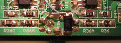
Aug, 2009: One day when plugged in, the two sites at the right indicated that they were charging, even though there were no cells installed. The switching regulator that supplies the charging power to that side was not putting out anything (it read about 0.9 V, while the other side's read 2.2 V). It turned out that the raw power was not getting to R36B (partially visible in the lower left side of Photo 3, above). Once again the twisting on the power jack with just normal plugging/unplugging had broken a track, this time the one to the left in the image above. This time I soldered a jumper to all of: the jack, D5, C9 and C9A. See Photo 4, below.

Photo 4. The new jumper. The jumper of problem 2 is in blue.
As well, I took the oportunity to “fix” the third problem at this time, I just removed the yellow piece of plastic that is supposed to actuate the switch. The switch now allows me to select the discharge function even though I have to use a pen or something else to push the button. To remove the bit of plastic, though, I had to remove the boards: when putting it back together I found it was not as hard to replace the positive cell springs as I had remembered...practice makes perfect!
If you wish to comment on this page, click on over to my contacts page  , and please do so.