What can YOU build today?
The utility of the Li'lBoard system is really in being able to build what you want when you want, and either end up with a system that is as permanent or as temporary as is needed. However, here are some suggestions to get you started thinking...
Some sample hook-ups.
1. Start simple: IR Remote checker:

This is a very simple hook-up, but can be quite handy. A Lithium coin cell (a CR2016, say) can provide enough voltage to drive an IR detector module if the Li'lBoard6.03 IR receiver module has a Vishay receiver installed. A Li'lBoard2.05 coin cell holder would make the cell easy to mount, but there there are also stand-alone holders for them. The configuration simply provides a visual indication of a TV/VCR/DVD/etc., remote control's functionality. The Li'lB6.03's on-board LED can serve as the indicator, or an external LED can be added. An on-off switch is probably needed. This will all fit in an Altoid Smalls case!
Mutations and other Possibilities:
- Any appropriate power supply could be used. A wall wart connector (i'lB2.08) could feed a positive linear regulator (Li'lB2.01) set for 3.3 or 5 V to power up the detector.
- This could serve as the first step in developing a µController-based remote control
decoder: add in a processor and start testing code to decode the
pulses. I've used a Li'lBoard6.03 with a Li'lBoard4.12 Li'Duino and Ken Shirriff's IR remote library
 with good success.
- Alternatively, the Li'lB6.03 could be pressed into service as a logic probe which will trigger on a negative-going pulse edge. This is because the on-board LED-driving circuit is a pulse stretcher. This use would likely require that the IR module be masked off or removed. The OUT terminal would then be the input (since the IR receiver's module has an open collector type of output this would not normally interfere if it is installed).
2. Headphone amplifier:

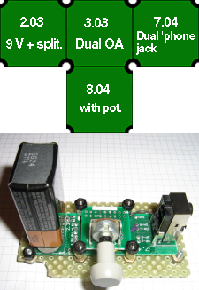
A C. Moy design headphone amplifier is easily built with a Li'lB3.03 (Dual Bipolar supply Op Amp), if a +/- supply can be generated. The Li'lB2.03 9 V battery module design includes a rail splitter for applications just like this.
In the sample that I built (shown), I used a Li'lB8.04 to accept the pins of a potentiometer which had 2 mm spaced pins. In that case, the Li'lB8.04 was mounted on top of the Li'lBoardB3.03. (See photo. The method of stacking two or more Li'lBoards was to use recovered male/female #4-40 spacers which were taken from an old PC motherboard that still had serial ports.)
The L'ilB3.03 component values and connections needed to create this circuit are:
- A good dual Op-amp installed. The OPA2134 is the usual choice for the C. Moy design;
- 1.0 kΩ at both R1 sites;
- 10 kΩ at both R2 sites;
- 1 µF 0805 capacitor at R3 sites
- 100 kΩ at both R4 sites;
- Jumper both -ve inputs to the ground;
- Inputs via a dual audio taper pot (10 kΩ to about 50 kΩ range).
Possibilities:
- Two 9 V batteries could be used, without the rail splitter. (Just use two 9 V battery clips.) Switching the power would require a dual pole switch.
- The circuit could be powered by a vehicle since the rail splitter can handle up to 40 V (but heed the warning re the voltage rating of C1 on the Li'lB2.03).
- 1 µF 0805 ceramic capacitors fit on the Li'lB3.03 at both R3 sites. The type of capacitor is said to make a great deal of difference to sound quality, so better polypropylene components could be used instead, soldered into the through-hole terminals at the R3 sites.
3. Utility charger:
So many devices (cell phones, tablets, etc.) now use a USB connection to charge their batteries and so many charge faster if more current than a standard USB port provides is available that producing (often bad quality) clones of USB power supplies is a big business. Why not build your own?
As well, so-called USB “decorations” are becoming ubiquitous. Why waste a whole USB port to drive a 5 V LED light or fan or whatever, when a 5 V supply does the same job? Put this together as an Li'lB2.01 fed by an Li'lB2.07 or an Li' lB2.08 depending on where you are and what power you have available, then feed the output to one or more A-style USB connectors (Li'lB7.11)
4. Function generator:
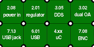
One of the most powerful Li'lBoards is the DDS function generator (Li'lB3.05). Based on the Analog Devices AD9833 DDS chip, a wide range sine/triangle/squarewave generator can be built up very quickly.

The configuration at the left is a function generator. The Op Amp is there to amplify the ~0.6 V output of the DDS chip up to a more useful level. The number of variations which could be made is, to use the old phrase, limited only by the imagination. (See “Possibilites” below.)
The assumed configuration would use a serial terminal program to “talk” to the μ Controller, which in turn would issue SPI commands to the DDS chip to set the frequency and select the output signal type.
The micro could be any of the possible designs, though many of them are bigger than the 1×1 size.
Possibilities:
- use a different controller or none (the later if there is an SPI port available on another µC in the system under test to take control of the DDS chip);
- many different power supply choices, including battery options, switching regulators, or just take the power from somewhere else via a terminal block. A single supply is assumed, but if the Op Amp board is changed to a Li'lB3.03 then dual supplies could be used;
- a different interface. An RS232, RS485 or LVDS transceiver could be used instead of the USB board, heck you could even use the spare remote control from the old VCR player that finally gave up the ghost, with an IR receiver module, the Li'lB6.03, to receive the pulses;
- a different method of control. If only a few output frequencies are needed, a push-button array could be used to select them, or, to create a full stand-alone instrument, a rotary encoder and LCD screen could be connected, or a surplus PC (AT) keyboard could be hooked up to the controller;
- direct wiring of the output into a system under test (delete the BNC connector).
Note that most of the control variations will require code changes to the µController. We do not supply these programs.
Some other circuit ideas:
- An old PC power supply could be turned into a multiple output laboratory supply using several Li'lB2.01s and Li'lB2.02s and even Li'lB2.04s if higher voltages are needed.
- A current limited power supply can be attained by feeding one Li'lB2.01 set as a current source into a second which is set up as a normal voltage regulator.
- A multiple current value LED tester could be built quickly using a Li'lB2.01 built as a current source, with the different currents (say 5 mA through to 100 mA in a 1-2-5 sequence) selected by a multi-pole switch.
- A fake car security system is easily build around a Li'lB3.01 and whatever colour of LED you want. Some kind of proximity detector (ultrasonic or just light level?) could be set up to change the flash rate.
- A real car security system would take some software and a controller, but could be built using the same components as the above as a starting point. A good illustration of the growth potential for circuits built with Li'lBoards.
- A windshield wiper delay module could be built with a Li'lB3.01 and a Li'lB5.06 FET board to drive the motor.
