Wiring methods for these little boards.
There are three main methods for interconnecting the boards:
- Soldering insulated stranded wires between boards;
- Installing female headers and using solid wire jumpers as in a solderless breadboard;
- Soldering in posts that can be plugged down into solderless breadboards.
Each method is illustrated below with photos. Generally, if method #2 is used it is still good advice to solder wires for the power and ground connections. The wires from multiple boards can then be brought into a terminal block board (a model 7.01) used to distribute power. I generally route the power and ground lines under the boards with the signals on top.
Method 1: Soldered wires.
The most reliable method is to solder stranded wires in the size range AWG #28 to #22 to the I/O pads as in Photo 1. The pads on power connections accept up to AWG #18.
 Photo 1.
Here an early version of the model 6.03 was tested with a pulse catcher/stretcher circuit built
on an early model 8.03 using all soldered connections. The signal wires and power between the
boards are on top, however the power from the outside world is routed under, to a model 7.01
for connection to a lab supply. The circuitry on the 8.3 is now part of the model 6.03.
Method 2: Solid Jumpers.
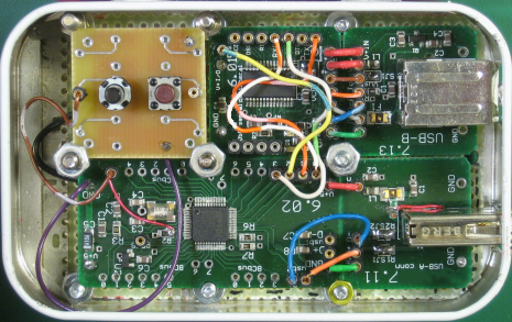
By soldering in common machined-socket (snappable) female headers the boards can be interconnected in a manner similar to a solderless breadboard socket strip as in Photo 2.
 Photo 2.
A demonstration USB controller commanded by a USB serial port. Here, AWG #24 or so
solid wires have been used to make the interconnections. In the case of the connections to the
model 7.11 USB A connector, either port of the controller can be selected just by moving two
jumpers. The board at the top left is an early prototype of what became the model 5.01: before
I added the LEDs there was room for 6 tactile push buttons. (Yes, this is all in an Altoids
tin!)
Method 3: With a solderless strip.
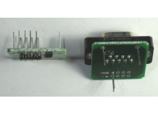
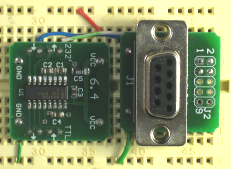
Many boards can be mounted on a solderless breadboard strip, Photo 3. In this manner the boards are acting as breakout boards. I prefer to not use “standard” (0.025 inch) header pins here since they only stress the spring-loaded contacts in a solderless breadboard; instead I use cut off LED leads which are smaller.

 Photo 3.
This pair of boards make up a RS232 transceiver with a DE-9 connector.
Left: Cut-off LED leads were soldered into the I/O and power supply pads as needed.
Right: All that is needed is to wire them up.
Photo 3.
This pair of boards make up a RS232 transceiver with a DE-9 connector.
Left: Cut-off LED leads were soldered into the I/O and power supply pads as needed.
Right: All that is needed is to wire them up.(These are both older designs: the new model 7.07 has an improved I/O pad arrangement.)
