A renewal of the Colour Clock design using 10 mm RGB LEDs and an Arduino.
It was about time. Almost every conceivable circuit is being based around the Arduino
system these days: why should my Colour Clock  be any different?
So I bought a cheap Arduino clone and built on! Besides just seeing how the design would go with
an Arduino, I had another goal, to create a version that could be used to test the clock concept's
effectiveness for a friend who is legally blind but can see somewhat. One symptom is tunnel vision,
so I decided to mount the LEDs on a backboard where their spacing could be varied somewhat so I
could test the effect of angular separation.
And a big change from the original was that I added an IR receiver so that a remote control could be used to control the intensity, set the time, and call up various test patterns.

The RGB LEDs.
Compared to 2003 when the original Colour Clock article was published, RGB LEDs have become not
only common but cheap! For the original circuit (which is still running just fine, thank you very
much) I had to perform a bit of DIY to simulate an RGB LED by shining a blue one through the body of
a Red/Green one. Not anymore. I bought a bunch of these  to try, and was impressed by how far the LED industry
has come in ten years. A great part, and at 36 cents each for just a few, a great price.
LED mounting.

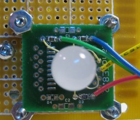
The mounting method had to allow re-positioning of the LEDs, and I wanted a black background to maximize contrast for the expected vision testing. I used four original model 8.02 Li'lBoards (designed to mount SOIC packages) since they accept the 0.050" LED pin pitch. Not shown in Photo 1, I simply spray-glued on some black card stock and I used black nylon screws and nuts.
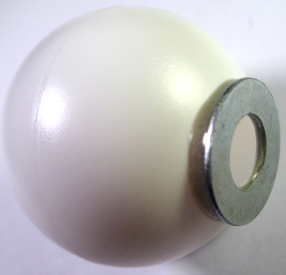
Once the LEDs were up and running I used some 5-minute epoxy to glue down some bits of that cheap flexible magnet strip that you can find. This was a perfect way to add some custom high tech LED diffusers (a.k.a ping pong balls!) which could be taken off at will. All that was needed was to cut out the right size hole in the balls then glue on steel washers which cleared the LED's flange diameter (Photo 2). (The ping-pong ball idea I picked up from HackADay, but I believe the addition of washers and magnets is my own addition.)
The rest of the circuit.
First implementation.
The original Colour Clock used a FET to drive each LED. Since there were 4 R/G LEDs and two blue ones, 10 FETs were required. I haven't gone back to the old design files to check, but I likely needed those FETs: microcontroller chips didn't have much output capacity back then. The ATmega chips used in Arduinos can handle an LED per pin, though. Even the pulse current, since all LEDs turn off and on at the same time, does not cause any problems to the outputs or to the chip as a whole. (The worst case current pulse is something like 4×2×20 mA = 160 mA, or if white were to be used, 200 mA.) So a significant saving on the parts count.
A single P-FET, then, switches the PWM-controlled curent to all the LED anodes. I used a dual FET board because that is what I had, but only the one is needed, and even that package is overkill.

Re-built with a Li'lDuino.
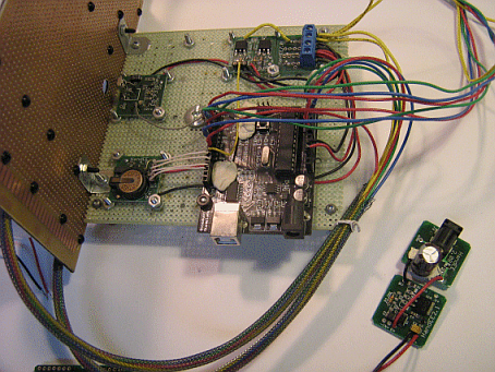
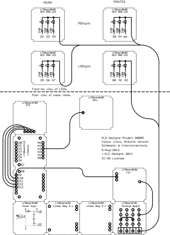
After the clock had been running for a while I finished the prototypes of the Li'lBoard4.12 Li'lDuino. So I just had to see how one of my own Arduino clones would work here. Turns out there were absolutely no problems migrating the build. And, since the Li'lDuino is smaller, and it matches the mounting array of the other boards, there were some space savings. This meant I was able to mount the pre-regulator and wall wart jack on the base board instead of having them hang loose. Instead of a photo, see Figure 1.

PWM considerations.
The original published design used a CdS light dependant resistor to control the PWM so that the clock did not bother people at night. I used a 10 bit PWM range there, but even then the lowest level is sometimes too bright when really dark in the bedroom. The normal Arduino PWM facility is only 8 bits. When I used this with a nice bright highest level the lowest visible setting was certainly too bright in a dark room. This was often circumvented by just turning off the display, which is the lowest intensity available in the implementation. The ATmegas, however, have the potential to go as high as 16 bit PWM using modifying Timer 1's set-up and calls.
So I tried a so-called 10 bit PWM mode. I found that the particular mode I used was effectively only 9 bits since the effect of both '1' and '2' on the period were the same. However, that 1 bit improvement (halving of the minimum brightness) was an improvement, but perhaps another 1 or 2 bits would be ideal.
The remote commands.
I integrated Ken Shirriff's IRremote library  into the code so that the clock could receive commands from a remote. I just used a cheap
“universal” remote set to a device which I do not have around the house as the
transmitter. It turned out that there were very few keys available for the chosen device, but
there were enough, with one spare left over (which got used...as such things will). The
table below is a summary of the commands.
| key | action |
|---|---|
| Pwr | RUN => SET mode; SET => RUN, keep changes, clear seconds. |
| CH+ | in SET: advance time by <step> in RUN: brighten LEDs. |
| CH- | in SET: decrease time by <step> in RUN: dim LEDs. |
| Stop | go from SET to RUN, making no changes, or go back to RUN if HALTed. |
| FF | increase <step>. (1=>10=>60=>1 sequence). |
| REW | decrease <step>. (1=>60=>10=>1 sequence). |
| PLAY | revert directly to 1 minute per step. |
| PAUSE | cycle between the normal 4-LED clock and the new 1-LED version. |
| 0 | show the bottom 2 LEDs only (horizontal discrimination testing). |
| 1 | show only the LS-minutes LED, i.e. bottom-right LED on (colour discrimination tests). |
| 2 | show only the minutes LEDs, i.e. 2 right-most LEDs on (vertical discrimination testing). |
| 3 | go to the "3" encoding which is my normal one. |
| 4 | go to the alternative, "4" encoding which puts the 4 colours on the (LS) bottom row. |
| 5 | * show all red (12:00). (“all” means only those which are enabled). |
| 6 | * show all green (4:20). |
| 7 | * show all yellow (8:40). |
| 8 | * show all blue! (special time code). |
| 9 | * shows 1:55, which is one of the 4-colour times, and is so in both encodings. |
* these cause a HALT condition which has to be terminated by the Stop key. HALT does not stop the clock, just the display.
Possibilities...
How about a 1-LED version?.
Since the reason behind this clock is to allow it to be read with poor vision, and since it relies on enough separation between the corner LEDs so that they can be individually discriminated, even if they are the same colour, I had a thought: what about presenting the colours in time instead of in space? I implemented this idea in this build of the clock (note the PAUSE command in the table), and found that though it worked, the idea has some negatives:
- The flashing can be annoying. It is not a friendly display when it keeps wanting your attention;
- It is somewhat harder to read the time and it takes longer to read too. One has to see all four colour time slots, and since the period that I used was 4.096 s and I found that I'd typically have to watch at least two whole cycles to be sure I'd read the colours properly, it could easily take 10 to 12 s to read the time;
- It would be more difficult to learn, I suspect. If all 4 digits are not apparent at the same time then it is not as clear how the display works. Since I already know how to read it, this is only a supposition;
- Since the code and procedure to set the time to the nearest minute also relies on a flashing LED (to indicate if one, two, three or four minutes should be added to the indicated time), there is an operational conflict here. I did not attempt to write code to set the time when using the 1-LED mode.
Note: I used 4.096 s as the period and designed the on and off times to fit within that. What I ended up with after one or two attempts was 1.0 s on, 0.10 s off, 1.0 s on, 0.10 s off, then 0.3 s on, 0.10 s off, 0.3 s on with the remaining 1.396 s off. I sent the digits in the most significant to least significant order.
Permutations and Combinations.
There is no real reason for choosing the order of the colours that I did. (Refer to the
main Colour Clock page  to be reminded of the sequence I did use.)
There was a reason, more than 10 years ago, for having as few blue LEDs as
possible—cost—but that reason has vanished now. (Having only 2 blue LEDs meant that they
were not in the first part of the sequence, so blue was necessarily last.) But now, if full RGB LEDs
are at each location, how many ways could the time be coded?
First, assuming that there are only 7 colours made by having only non-zero combinations of the RGB
LEDs on (in other words excluding black), and that the least significant sequence (of 3) is the
same sequence with one (the last) dropped off, there are 7×6×5×4 = 840
possible choices of unique 4 colour sequences! (That is 7P4, 7-permutated-4, in one
common notation.) If the assumption that the LS sequence is allowed to be different than the MS
sequence—and one's brain is up to this—then the total is 7P4×7P3 = 840×210 = 176,400!!
Wow. That means that every resident of a small city could use a different encoding.
How's that for personalization? {I won't go on to the probably pointless possibility of using
different sequences for the hours vs. the minutes dispalys!)
I toyed with the idea of making the sequence user-definable in this version (though I was not about to go with the second choice, just the 840 possibility case), but I realized that I was coming up against some limits: both the code space in the ATmega168-based Li'lDuino and the number of codes from the remote were maxing out. Maybe there would be enough space for the extra code to use the Li'lDuino's EEPROM, maybe not. (It might be OK to use the EEPROM instead of the RTC's backed-up RAM to hold all the stored data, I felt that the likely number of write cycles could be a real limitation—I change the LED intensity quite often, for example.)
24 hour mode?
If a 5-colour sequence chosen instead of the 4 and 3 sequences, then 25 combinations exist. Five colours are easily discriminated as things are now—probably the best colour to add is “white” with all LEDs on. This would allow a 24-hour clock. But, either the hours and minutes columns would use a different encoding which would be harder to learn, or, if each hour were divided into 24 parts instead of 12 then the resolution of the minutes would be 2.5 minutes: not very natural. Tough choice.
Another approach might be to stick with the now-standard (standard to me and several members of Makerspace Nanaimo at any rate) sequences but use a 5th light for am/pm. Just like millions of alarm clocks. One idea would be to use a white backlight which is only on for half the day...doesn't have to be any particular half day.
