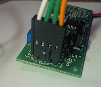
ChronulatorSMD boards shipped for “The Volt” clocks.
Table 1 details the set-ups for all the boards delivered for the
Kickstarter Volt Clock  project by Kyle Miller.
| Table 1. | ||
|---|---|---|
| Board serial number(s) | Hardware set-up. | Software set-up. |
| 4019, 4020, 4021, 4024, 4025, 4026, 4027, 4028, 4029, 4030. | Processor: ATmega168V Meter set-up parts: 10 kΩ, 1% resistors in parallel with the 51.1 k SMD parts at R4 and R5, and 5 kΩ trim pots at P1 and P2 Battery holder: Enclosed model (with switch). Additional notes: • The 32 kHz crystals were NOT glued down: they likely should be [1]; • The tracks at SJ5 were not cut: they should be if running from a battery [2]; • Cable length approx 6 inches/15 cm. |
Bootloader: “LilyPadBOOT_168.hex” Application: “pm2v-flash-2.01-200812090122.hex” |
| 4013, 4016, 4017. | Processor: ATmega168V Meter set-up parts: exactly as above. Battery holder: Enclosed model (with switch). Additional notes: • The 32 kHz crystals were glued down; • The tracks at SJ5 were cut: they may be re-joined if serial communication is wanted; • Cable length as above. |
Bootloader: “LilyPadBOOT_168.hex” Application: “pm2v-flash-2.01-200812090122.hex” |
| 4034, 4035, 4036, 4037, 4039, 4040, 4041, 4042. | Processor: ATmega328P Meter set-up parts: 10 kΩ, 5% resistors in parallel with the 51.1 k SMD parts at R4 and R5, and 5 kΩ trim pots at P1 and P2 Battery holder: Open model Additional notes: • The 32 kHz crystals were glued down; • The tracks at SJ5 were cut: they may be re-joined if serial communication is wanted; • Cable length approx 4 inches/10 cm. |
Bootloader: “ATmegaBOOT_xx8_chronSMD328.hex” Application: “Chronulator_AVRmod-PCorr.hex” This software uses the phase correct PWM mode to give zero meter deflection at zero value. |
| TBD | Processor: ATmega328P Meter set-up parts: Battery holder: Open model Additional notes: • • |
Bootloader: “ATmegaBOOT_xx8_chronSMD328.hex” Application: “” |
| TBD | Processor: ATmega328P Meter set-up parts: Battery holder: Open model Additional notes: • • |
Bootloader: “ATmegaBOOT_xx8_chronSMD328.hex” Application: “” |
Notes from the table:
- [1] just a small dab of hot glue is all that is needed, see [PHOTO 1].
- [2] see [PHOTO 2]
 Photo 1.
A little
daub will do you.
 Photo 2.
Cut for
lowest current.
Some details which apply to all boards.
 Photo 1.
A little daub will do you.
 Photo 2.
Cut for lowest current.
The cables are made up of two green wires (the grounds), one orange wire, and one white wire. The convention I'm using is that the 4-way plug connects to the 4-way header at SJ1 with the keying protrusion away from the board [PHOTO 3-TBD]. That way the white wire connects to the hours meter and the orange to the minutes. No damage to the meters will result if the connector is rotated the other way.
 Photo 3. Cable
orientation.
Page visited: Saturday, May 17th, 2025 at 4:15pm PST. Last updated: Nov 2, 2018.