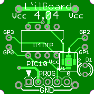
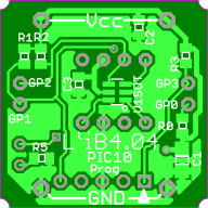
SOT-23-6 PIC Li'lBoard page.
Model number: LB4.04.
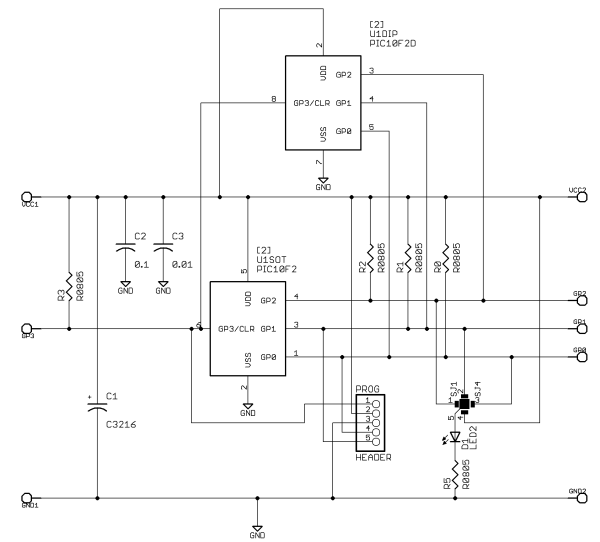
Description: A PIC in a microscopic package. Eight possible parts: PIC10F200 through '206, and the '220 and '222, with the newer '320 and '322 parts untried so far. The board is designed so that either the SOT-23, 6 pin package or the 8 pin DIP can be installed: either side can be “up”. A special 4-way solder blob “switch” allows an on-board LED to be connected to any of the 3 output-capable pins or just to the Vcc rail.
Applications: Any application where only 4 I/O pins are enough (3 I/O and one In, actually.) Code space is either 1/2 Kwords or 1/2 that.
Features: The board can be used with either side up depending on which package is being used.
Key components:
Optional processors are:
•PIC10F200 256 words of Flash, 16 bytes RAM, 3 I/O, 1 I, 1 8-bit timer
•PIC10F202 512 words of Flash, 24 bytes RAM, 3 I/O, 1 I, 1 8-bit timer
•PIC10F204 256 words of Flash, 16 bytes RAM, 3 I/O, 1 I, 1 8-bit timer, comparator
•PIC10F206 512 words of Flash, 24 bytes RAM, 3 I/O, 1 I, 1 8-bit timer, comparator
•PIC10F220 256 words of Flash, 16 bytes RAM, 3 I/O, 1 I, 1 8-bit timer, 2 8 bit ADCs
•PIC10F222 512 words of Flash, 24 bytes RAM, 3 I/O, 1 I, 1 8-bit timer, 2 8 bit ADCs
•PIC10F320* 256 words of Flash, 64 bytes RAM, 3 I/O, 1 I, 2 8-bit timers, 3 8 bit ADCs, etc
•PIC10F322* 512 words of Flash, 64 bytes RAM, 3 I/O, 1 I, 2 8-bit timers, 3 8 bit ADCs, etc
* new devices, have not been tried with the board, nor is programming support available in PICkit2 or 3 (Nov 2011).
Restrictions: If the SOT-23-6 side is up then the 4-way LED solder-blob header is not as accessible as when the DIP side is up since that header is on the DIP side.
Images:


SPI: Potential host.
Tenth centers: YES

