A method to handle multiple input switches with a minimum of Arduino inputs.
I had a requirement to enter a time from a panel into a count-down timer in a system I was
building. I was using an Arduino Pro Mini. I had on hand some appropriate thumbwheel switches
which fit the panel very nicely, so I took a look at using them. At first, the switch collection
appeared to be [+/-][0/1][0...9][0...9][0...9] however when I removed the not-needed [+/-] switch
I realized that the right-most switch was an odd one since it had just one output: it is in fact a
[0/5]. That was OK for the application since a 5 minute resolution was just fine (and if you have
seen my colour clock  you will know that I feel that 5 minute
resolution is good enough). So, there are two one-bit switches and two BCD coded switches. That
would require 10 input pins if read directly or 2 outputs to a 1 of 4 decoder and 4 inputs, or 1
output to select either half of the 10 switches and 5 inputs. Both of these would need 6 pins.
you will know that I feel that 5 minute
resolution is good enough). So, there are two one-bit switches and two BCD coded switches. That
would require 10 input pins if read directly or 2 outputs to a 1 of 4 decoder and 4 inputs, or 1
output to select either half of the 10 switches and 5 inputs. Both of these would need 6 pins.
So I looked into the two classic methods of creating analog values using resistor networks. Those methods are the R-2R ladder and the binary-weighted resistor tree. Consulting The Art of Electronics [3rd Edition, pages 882 & 883], one sees similar figures to these:
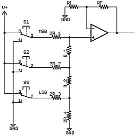
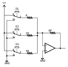
Note that both circuits as shown here use an op amp. Since I'm trying to keep this as simple as possible it would be desireable to feed the Arduino analog input directly. Also note that both circuit configurations use double throw switches: that is not how most thumbwheels are made! So now it comes down to: can either of these circuits be operated with just single throw switches and no amp?
First, let's check the R-2R case (it is, by many metrics, the better of the two choices: in fact the authors of The Art state that the other configuration is “never used in practice”). Let's look at whether the switches can be single throw here by seeing what happens if the switches only connect to the positive voltage, not to ground. Some basic analysis showed me: NO. If S1 is connected to V+ and the other two are open (a binary code of 100) then 2/3 of V+ is produced at the node feeding the op amp, and if that is left open while the others are closed (code 011) then 3/4 V+ is produced, clearly not monotonic, and the proper values should be 1/2 V+ and 3/8 V+.
So can the binary-weighted resistor network be made to work? If you understand basic op amp circuits, you will know that the -ve input here is a virtual ground and that this node is simply summing the currents produced by the positive reference voltage across whichever resistors are connected to it: connecting these to ground adds nothing, so single throw switches are just as valid. So far so good. However, deleting the op amp, making the switches single throw and connecting to an input pin does nothing useful: if any combination of switches are on then the voltage will simply be high and if all are off then the pin is open. Not good. So what is needed is an alternative current to voltage converter to replace the op amp. A resistor does that!
Implementation.
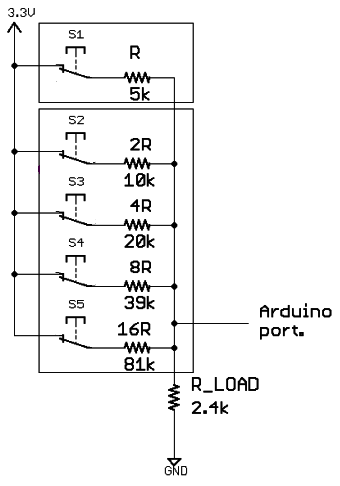
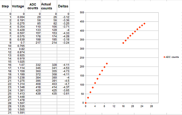
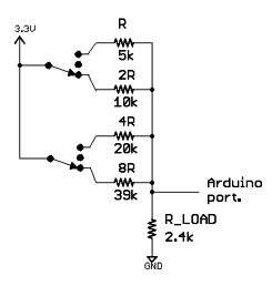
Figure 3 shows what I ended up with for half of the thumbwheel set. I used basic 5% parts. The load resistor was chosen to be close to equal to all the 5 values in parallel so that the full scale voltage would be near 3.3V/2. Figure 4, below, shows both calculated and Arduino-reported values for all 20 switch positions. The fact that the most significant bit defines two distinct regions was useful: I used two separate map() statements to do the decoding as shown in this code fragment.
if (tw_high < 271){
  tw_hr=map(tw_high,0,200,
        0,9);
}else{
  tw_hr=map(tw_high,320,430,
        10,19);
}
tw_high is the value read from the analog pin and tw_hr represents the setting of the 2 most-significant switches and is eventually loaded as the hours value into a counter variable when a button is pushed. The values were arrived at with some trial and error, simply based on the Arduino-read values, but they seem to be stable. A more detailed analysis of the margins could be done. Luckily the curve sections are linear enough for this to work.
Got a lot of thumbwheel switches to read?
To generalize this idea, at least as far as thumbwheel switches are concerned, I'd say that if a single analog port can be allocated to each BCD decade then this would be a very efficient technique. If one had a large number of these, then an analog mux could be used to read one digit at a time. Say 16 digits were needed: then only 1 analog input and 4 digital output pins would be needed. Economical indeed. If one is interfacing to that many, then probably a smaller Rload followed up by a voltage gain to boost the output range up to nearer the full range would be helpful. It is NOT likely that two BCD switches could be read using 8 resistors (the ratio of largest R to smallest is 128:1), though if the same lower value load resistor followed by a positive gain idea was used, and perhaps 1% resistors, then I expect it would be feasible to read 6 switch-lines this way.
An even easier version of the idea.
The same panel required that two 3-position switches be read by the Arduino. The switches I had on hand were DPDT but with a center-off position.
The map() function was of no help decoding these, but since there are only 9 possible states it was fairly easy to use a bunch of if statements to decode:
 int sw= analogRead(SW3_IN);
 if(sw<184){
   left = M;
   right=H;
   if(sw<59) right=M;
   if(sw>89) right=L;
 }else if(sw<332){
   left = H;
   right=H;
   if(sw<229) right=M;
   if(sw>268) right=L;
 }else{
   left = L;
   right=H;
   if(sw<363) right=M;
   if(sw>390) right=L;
 }
Again, the thresholds were decided upon by using Arduino-reported values for each of the reachable states. Before the code fragment above, the right and left variables were created as enumerated types:
enum sw3_states {
  H,M,L
};
enum sw3_states left, right;
So. A clear reduction in the number of port pins needed. Either 4 direct digital inputs or 1 output and two inputs would otherwise be needed to read these two switches.