A deviation from the norm: a non multiplexed 7 segment LED display
I decided I wanted to build a tachometer for the metal lathe at my Makerspace. Four digits seemed sufficient. My "go to" Arduino version, the Pro mini, seemed like it should do the job, and I had come across a few 7447 TTL BCD to 7-segment decoder ICs, so I took a look at using 4 of these instead of just one and a mux scheme.
Obviously the number of I/O pins is of concern here. It worked out OK, though, but essentially all of the I/O is used. (To be complete, though, the two pins normally used for serial I/O are still available, but using these complicates debugging.) When I decided I needed to be able to show decimal points things got tight: I was able to use the last available pin to drive a pair of FETs which allowed one or the other of the two lowest position decimals to be on.
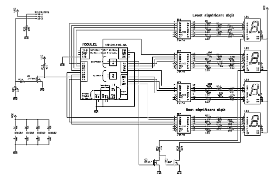
The schematic follows:
Construction,
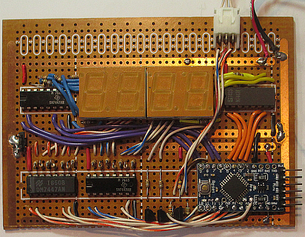
As can be seen in the first photo below the circuit was soldered onto a section of DIP-oriented perf board. A pair of power input wires and a 3-pin connector for the sensor are the only off-board connections. The manufacturers and date codes of the chips is interesting: two TI parts from 1976, one newish 1985 National Semiconductor chip and one very vintage 1971 Signetics part, all happily living beside, and being fed by, an Atmel ATMEGA328 from this decade.
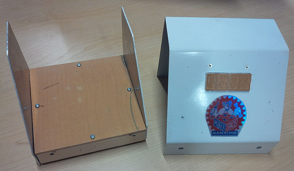
The case was made from Aluminum which was cut and bent using the Makerspace sheer and brake respectively. The base of the unit was made of a wooden frame filled with cement: a neat trick to make a project seem more than it is, but more importantly in this case, to help it be immune from the machine's vibration. (This characteristic was aided by glueing on a piece of rubber mouse pad on the bottom of the cement.) Not shown, on the back of the case are a power jack, a power switch and a 3-pin metal-body connector for the sensor. An LM317-based regulator is also attached inside to the back to drop down the wall-wart supplied 9 or so Volts to the required 5. If the right hand panel is removed then a programming cable may be easily attached to the Pro Micro.
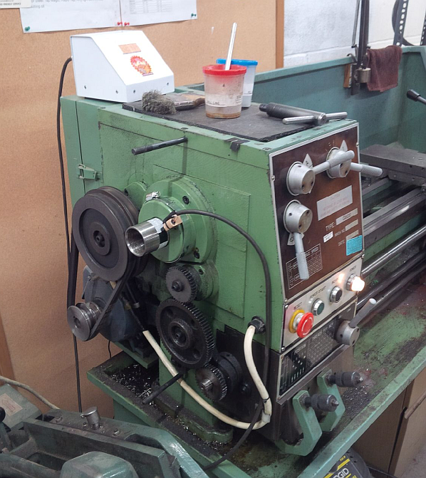
Installed on site, with the lathe's change gear cover off, the sensor positioning and high contrast reflective strip can be easily seen. The sensor is an IR reflective type, mounted in to a drilled and shaped chunk of wood which in turn is mounted to the bearing cover with a hose clamp.
The firmware.
First, a lot of pins need defining! Note that the colours of the wires to the decoder, and from the decoder to the displays are shown in the commented code for each digit.
//  PINs:
const int TACH_PIN=8; //see comments below: no choice!
//digit 1 (wired violet=>blue)
const int LSD_A = 2;
const int LSD_B = 5;
const int LSD_C = 4;
const int LSD_D = 3;
//digit 2 (wired wh/blue=>wh/blue)
const int nLSD_A = A4;
const int nLSD_B = A1;
const int nLSD_C = A2;
const int nLSD_D = A3;
//digit 3 (wired wh/orange=>wh/orange)
const int nMSD_A = A0;
const int nMSD_B = 11;
const int nMSD_C = 12;
const int nMSD_D = 13;
//digit 4 (wired orange=>yellow)
const int MSD_A = 6;
const int MSD_B = 10;
const int MSD_C = 9;
const int MSD_D = 7;
//and the last pin is the decimal point:
const int DP = A5;
//values for the DP:
const bool X1  = true;
const bool X10 = false;
//variables and constants:
const unsigned long DROP = 800; //wait this long for any counts: if none, go to 0.0
const unsigned int PULSES_PER_REV = 4; //4 on, 4 off per rev.
const float FACTOR = 60.0/PULSES_PER_REV;
volatile unsigned long event;
volatile int event_count = 0; //range 0...9, with 10 transient inside ISR.
int last_caught_change;
volatile bool enough=false;
const int EVENT_MAX =104;
unsigned long event_set[EVENT_MAX];
unsigned long deltas[EVENT_MAX];
volatile byte changes_index;
volatile bool clear_it=false;
volatile float last_rpm;
Skipping over the setting of all those pins to OUTPUT mode, the next important part is setting up the 16 bit timer. It turned out that with the speed range of the lathe (60 to 1550 RPM), and either a 16 MHz or 8 MHz crystal choice for a Pro Mini, the 8 MHz choice worked out better! Sometimes faster is NOT better. Note that there is no problem operating a Pro Mini which is set up to run at 3.3 V on 5 V.
  /* set up timer 1 (the 16 bit one) to be 1 MHz clocked. Needs to count BETWEEN
   * edges (assume rising edge to trigger) CS10, CS11, CS12 need to select /8.
   * These are 3 LSbits of TCCR1B. Need CS1x= B010 for divide by 8. For rising edge
   * input capture set bit 6 to 1. N.B ICP1 is PB0. That is the only pin that can be
   * used to trigger a 16 bit counter capture. Luckily that is D8 in Arduino land.
   */
  noInterrupts();
  TCCR1A = 0; //Compare output mode and waveform generation bits: not used here.
  //TCCR1B bit definitions:
  // 7 ICNC1 noise filter; 6 ICES1 IC edge select, 0 is falling edge; 4-3: WGM;
  // 2-0: Clock select, used here
  TCCR1B = 3; //2: s/be CS12:0, CS11:1, CS10:0: ClkI/O divided by 8.
  // **now: =3 is div by 64, 8 times slower
  TCCR1C = 0; //only 2 bits defined to force output bits: not used here.
  TIMSK1 = 1<<ICIE1; //ICIE1 only.
  interrupts();
So the 16 bit timer is set to count the number of internal 1 MHz clocks between rising edges. At 60 RPM 4 of these intervals are 1.0 s since there are 4 pulses per rev on the reflective strip. At the highest speed one revolution is about 39 ms
Before we can begin, an interrupt has to be set up to react to incoming pulses. The variable changes_index is the key to enabling a wide count range: it holds a value which determines how many samples of the pulse duration are needed to make up a reading. An array, event_set contains all the readings: more are stored at higher speeds.
// The interrupt:
ISR(TIMER1_CAPT_vect){ //declare the interrupt service routine
  event_set[event_count] = ICR1; //read the capture register (special 16 bit read)
  event_count++;
  if (event_count == 1+(changes_index+1)*4){
    //5, 9, 13, 33, 49 => 4, 8, 12, 32, or 48 measurements
    enough = true; //set, as a semaphore
    event_count =0; //wrap around
  }
}
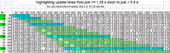
As noted in the comments in the above snippet, the size of the set of samples varies. The sizes used were determined by a speadsheet so that a nominal display update period of between 1/2 s and 1.25 s is always seen. In the spreadsheet, sampled below, the rows represent how much time is needed to gather N samples (N+1 in actuality) from the sensor. Sections on each line are highlighted in a colour to show only times betweenthese limits. A somewhat arbitrary set of Ns were chosen so that there was some overlap: these are highlighted in turquoise. These 5 numbers (4, 8, 6, 32 and 48) make up a set of sample counts which can be used to obtain a display update period within the desired range.
The routine below handles the switching of the number of samples needed for a measurement. You can see that it is tied to the values from the spreadsheet directly. It is called once after a reading is displayed, near the end of loop().
void set_sampling_rate(float rpm, float rpm_last){
  // Change the required number of samples to adjust the update time and quality
  // of averaging as a function of the speed. Did jiggle back and forth if changes
  // in the reading were such that two settings were valid: so addded multipliers
  // 1.01 and 0.99 to the code below to alleviate this.
  if(rpm > (rpm_last*1.01)){
    switch (changes_index){
      case 0: if (rpm > 120) changes_index = 1; break;
      case 1: if (rpm > 240) changes_index = 3; break;
      case 3: if (rpm > 420) changes_index = 7; break;
      case 7: if (rpm > 600) changes_index = 11; break;
    }
  }
  if(rpm < (rpm_last*0.99)){
    switch (changes_index){
      case 11:if (rpm < 1020) changes_index = 7; break;
      case 7: if (rpm < 540) changes_index = 3; break;
      case 3: if (rpm < 300) changes_index = 1; break;
      case 1: if (rpm < 180) changes_index = 0; break;
    }
  }
}
The essence of the logic is in loop(), as is typical in Arduino sketches. Note the disabling of only the one interrupt: don't want to mess with the other counters, especially the one providing the millis() function.
Two function calls are highlighted in red below: one you have seen, the other drives the display using BCD numbers.
void loop() {
  byte count;
  float accum, rpm;
  unsigned long rpm_i;
  if(event_count != last_caught_change){
    event = millis(); //when was this?
    last_caught_change = event_count; //update the caught count
    clear_it = false; //don't zero the result
  }else{ //nothing new this time since count still the same, but
    // might need to clear the result.
    unsigned long maintenant =millis();
    if (maintenant >(event+DROP)){ //waited too long!
      clear_it = true;
      show_speed(0.0);
    }
  }
  if (enough){ //ISR says: we have had sufficient samples to declare a reading
    TIMSK1 = 0; //disable the interrupt
    accum = 0.0;
    count = 0;
    for (byte i=0;i < (changes_index+1)*4; i++){
      if(event_set[i+1] > event_set[i]){
        accum = accum + (float)(event_set[i+1]-event_set[i]);
        count++;
      }else{ // overflow allowed: can happen when counter wraps
        accum = accum + (float)(65536+event_set[i+1]-event_set[i]);
        count++;
      }
    }
    enough = false; //have processed it...
    if(clear_it){
      rpm = 0.0;
      changes_index = 0; //since we stopped need to prepare for fast
      // reading at slow speeds again
    }else
      rpm = FACTOR/(8.0E-6*(accum/(float)count)); //div by averaged time [s]
    show_speed(rpm);
    set_sampling_rate(rpm,last_rpm);
    last_rpm = rpm;
    TIMSK1 = 1<<ICIE1; //enable the interrupt again
  }
}