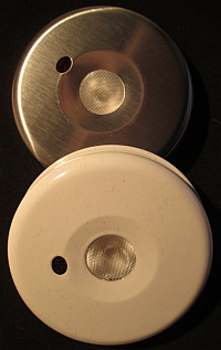
Photo 1. A pair of Dragons
A great deal!
I found that a local store was clearing out their stock of Sylvania Golden Dragon
under-counter LED lights. I knew that these had previously retailed for about $16 (Cdn), and I
knew that I had once paid almost that same price for a single Golden Dragon LED from Digi-Key. So
when I saw these for less than $4, I knew I had to buy some. In fact I bought up all they had! The
lights were (Feb 2013) listed on Sylvania's site  for about $17, but that site is gone now (2016).
It turns out that the LEDs used are even brighter versions than that one I bought years ago, these are 3 W bulbs, not the 1 W version that I had bought! I bought (one and only) one of the LW W5SG units but these seem to be something like the LCW W5SMs. These, or something like them, have come down in price a huge amount: the 1 A ones can be bought for about $2.50 now.
What they are
These lights are kind of neat. They operate with the wave of a hand or other object, as long as the object is reflective enough and as long as it passes by within a few inches. There are two light levels which are attained in sequence, high, then low, then back to off. The illumination does not change until the object is taken away and the reflections stop. The lights are in a two-piece steel case, either white or with a brushed metal finish and come with a thin, large diameter magnet which has some 3M double sided adhesive on one side. The magnet is meant to be stuck to the bottom surface of a cabinet, such as over a kitchen counter. They are powered by 3 AA cells.
Circuit, Reverse Engineered
A few minutes with a beeping DMM revealed the complete circuit:
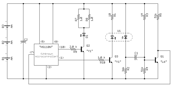
Figure 1. The light's schematic.
The biggest mystery, at the hardware design level, is what the heck is that processor? It is in a
5.0 mm by 4.0 mm package with 10 leads which are spaced at 1.0 mm. I found one
reference to somebody else looking for the same chip on the EEVblog forum (but a totally different
application), which was not resolved, so I added to the thread , and a probable device was identified, but not it seems, until I posted the present page on
the forum as well. Interesting that a 10-pin device is being used when only 3 I/Os are required.
One of the PIC10F200 family would do the job here.
A smaller mystery revolves around the two transistor types: I could not find a translation for the “Y1” type used to drive each LED, but I found some evidence that the “L6” type at the IR receiver is similar to a 2N3904. Regardless I am confident that both types are NPN BJTs.
All resistors and capacitors are the 0805 size. The resistors are aparently 5% tolerance. The capacitors are of unknown values, but it is safe to say, based on the body height and circuit functions, that C2 is a larger value than C1.
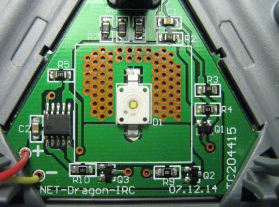
Photo 2. Circuit board with lens holder removed.
Timing measurements.
The 'scope tells me that:
- The two different brightnesses are obtained by using PWM periods of about 80% and 20%, and in fact the signals are complimentary. The PWM period is about 4 ms, so 250 Hz.
- The reflective sensor's IR LED is pulsed for about 20 µs every 20 ms when the main LED is off, but when the LED is on it is pulsed at every fourth PWM cycle, so every 16 ms.
- Interestingly, when a reflective object is close to the sensor, a second pulse is sent out about 45 µs later and both pulses are about 10% longer.
- It looks like the firmware is running timing loops not timer interrupts since the period between the IR LED's pulses change as a function of the white LED's state.
One thing I have not done is test the response of the circuit to an external simulation of the pulses as received by the reflection sensor. The reason that I am curious about this is that two of these units, set up face to face, trigger each other! I discovered this when I had one looking down on my desk and absently put another below it and they both started, slowly, cycling through their states! They were about half a meter apart. I initially presumed that this implies that interrupts are being used on the receiving side, because the chances of the two being in sync is in the order of a thousand to 1. So, I supposed, that signals fed into the input port of the processor, and with timing similar to what is sent out, but with no syncronization to the timing of the pulses sent, would be recognized as valid. But maybe not: consider that the pulses have to stop for the circuit to change state, so either they are drifting in and out of sync or something else interesting is going on...where's that pulse generator?
Another thought here: the frequency of the pulses is either 62.5 Hz when the light is off, or 50 Hz...aren't these too close to mains frequencies to be immune from flourescent lighting if there is no synchronous detection? And even if there is? I guess the receiver, whether it is LED or transistor, could be fairly immune to visible light.
Current and power measurements and calculations.
Now it does seem that running a 3 W LED from 3 AA cells is a bit of a stretch. One design decision that was made to alleviate the battery drain is that the unit turns itself off after a period—but that period is an hour! An order of magnitude calculation based on a bench supply-driven consumption test was that fresh cells should only last about 4 hours. I measured an average current consumption of 300 mA on high in that situation (fortuitously I was driving the current with rather thin wires from the supply—it appears that if I had driven it from a very low impedance at 4.5 V then the current limiting resistors could have gotten “quite warm”—maybe even to the magic smoke stage!).
- A simplistic calculation (3.2 V for the LED, a VCE(SAT) of 0.5 for Q2 and 4.5 V total for the cells) yields a LED current of 1.6 A so clearly the impedance of the cells is important! (See next point.)
- Running from the AA cells the rail voltage measured near to the white LED D1 drops about 1/2 V when the LED is being driven.
- The 10 Ω resistor in series with the IR LED seems quite low. The “off” consumption was measured at about 50 µA, so It seems that, since the duty cycle on the IR LED is 1 in a 1000, that it must draw almost 50 mA during each pulse.
- The thermal design for the Golden Dragon LED relies on a good heat path from the chip to the
back of the metal case. There are several elements to the thermal path:
- The LED's anode is connected to a large pad on the bottom of the package as well as to the lead at the top of the chip in Photo 2. The PCB has a fairly large thermal via directly under this pad, and it is filled with a nice filet of solder.
- The PCB is fairly thin at almost exactly 1.0 mm.
- There are multitudinous thermal vias through the board near the LED, which can be seen in Photo 2 quite clearly.
- The bottom of the board is thermally connected to the inside of the case with some thermal grease.
- The case itself, as mentioned, is metal, though there will not be any significant air flow over it considering the typical installation site.
How I would redesign
It is always a danger when somebody like me comes across something like this: the temptation to redesign is endemic! I'd probably do the following:
- I'd swap the state sequence, in other words I'd have it come on at the lower power setting first.
- I'd use a processor that I know such as a member of the PIC10F200 family.
- I'd consider a thermal sensor near the LED. Even with one more input the smaller processor would still handle the design.
- I'd try to ramp up the brightness depending on how long the reflective hand was present, something like if the reflections lasted for a time below a threshold of say, 1/4 s then cause a step when the signal goes away, but if it is there longer ramp it up (if off) or down (if on past a certain threshold).
- I'd shorten the time-out period, and in fact just cut down the power, say a half, for every timeout interval. So if the interval was 15 minutes it would go to half power, after 30 then to 1/4 power, etc. After an hour then the level would switch to only 5% and the power used for the hour would be about 47% of the original scheme. Besides saving power, this scheme would be safer and less annoying.
- I'd consider running from an external supply with the AA cells as backup only.
Well, I need another project like I need a third arm—hey wait, that could be useful—but no promises…!