A Colour Clock for Makerspace Nanaimo.

Using the same display style as previous clocks I've built (here  ,
which was published in Circuit Cellar magazine, and here —an update of the original design using an Arduino), I built a
clock for Nanaimo Makerspace.
,
which was published in Circuit Cellar magazine, and here —an update of the original design using an Arduino), I built a
clock for Nanaimo Makerspace.
This was to be a large installation, at one end of a fairly large room. Besides the size the packaging and installation had to be considered since it was going into a semi-public space.
The LED displays.
Obviously a larger display was needed than what I'd built for the night stand versions. The dollar-store ping-pong balls used in the first Arduino version had worked so well that I went back to see what else I could find. I decided that those cheap push-on push-off lights meant to be used in places where occasional illumination is needed would work.
Dissassembly of the lights and the design of a PCB to go inside these ensued. I went to a “quick turn” PCB manufacturer to get some no solder-mask boards made. Very simple circuitry, just 5, 10 mm RGB LEDs driven in parallel. There's a P-channel FET to provide local control of the power in an effort to minimize EMI, three N-channel FETs to drive the LED colours and resistors to limit the LED currents at each LED. Power (5 V) and ground, three lines for the LEDs and another line carrying a master PWM signal were brought into each PCB.
A home for the electronics.
I decided to integrate the electronics into a version of our wonderful (thanks, Trevor!) logo
which I'd have to make. I'd also recently bought some
very cheap Arduino Mini clones  , and I'd had a
ChronoDot given to me.
Both of these seemed to fit into the logo well. Needless to say the making of the logo was at least
as much work as the building of the electronics.
, and I'd had a
ChronoDot given to me.
Both of these seemed to fit into the logo well. Needless to say the making of the logo was at least
as much work as the building of the electronics.
The worst aspect of the woodwork was the fact that I reused some particle board which I had lying around. Not a great material to work with, even MDF would have been better since the finer particles in it would have sanded more cleanly.
I used a technique which surprises people to get the full colour logo onto the wood: over-head view-graph transparencies printed on a colour laser printer. (These sheets are becoming harder to find since presentation-software-driven video projectors have taken over this ecological niche, but fortunately we have boxes of these sheets in stock.) Unfortunately the size I chose to make the logo, 16" by 16", meant I had to use four sheets and cut them carefully so they would but against each other. The main secret of this method is to left-right reverse the image before printing. That way the toner is on the back side of the transparency so it resists scratching.
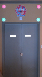
Installation.
The installation proved to be more difficult than expected. Sure I expected that there'd be studs in the wall, but I did not expect that there could possibly be be a third sheet of drywall between the two normally required for a wall! Thanks to Matt for the advice to fish the wires through the entire wall instead of trying to go sideways through the studs.
The LED assemblies are wired to the central location by custom-made 6-wire cables which are soldered to the PCBs in the LED units. I thought I had made the cables long enough for any eventuality but when it came time to fish wires, one of them had to be extended and another is too short for comfort. A connector at both ends would likely have been better, though more to go wrong.
Future Plans.
A couple of items for the future:
- The electronics has a light-dependent-resistor mounted and I have checked that it is read by an Arduino analog pin, however there is no connection in the software between ambient light and the LED PWM control;
- I'll probably re-make the cables between each LED and the central control site, putting connectors at the LED end as well.
Development Support.
To re-program the Arduino mini clone, I made a 12 foot long extension cable to run between the FTDI USB to serial board and the Mini. I did not want to make software changes balancing my laptop on top of a step ladder! This cable has worked just fine the couple of times I've used it.
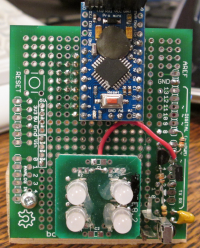
In support of these future changes and because I had 4 RGB LEDs already mounted on a little board, I also made up a miniature version of the clock [Photo]. There's a real-time clock chip board on the back side which is similar to the ChronoDot in that it uses the same commands.