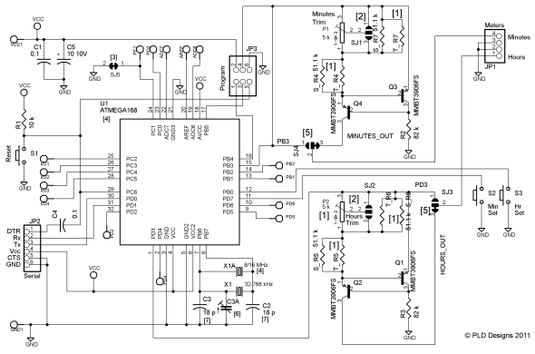
The schematic.
Here's the schematic. There are only a few differences from the original, mostly made to reduce the size of the board:
- The resistors that define the current sources are configured differently to make software selection of component values easier;
- These same resistors are designed as parallel pairs: one component of each pair is an SMD resistor, the other is a site designed to take an 1/8 W through-hole part;
- The method of getting power into the board is simpler, no power connector and no header to switch between battery or USB-originating power. The user has to be a little bit careful when changing power origins;
- Related to the previous point, the way of deciding whether the serial code is able to run is different: it is not enabled by external (non battery) power, instead it can be enabled or disabled independantly;
- The large potentiometers which were used to fine tune the current sources are now "trim pots." As well they can be either top or side adjust and can be mounted on either side of the board. Solder blob jumpers allow the control direction (whether the current adjustment increases clock- or counter- clockwise) to be set regardless of how they are mounted;
- There is no provision for mounting meters on-board, they have to be wired to JP1, a 1×4 header;
- The current sources can be bypassed so that some off-board circuitry can be substituted. The same 1×4 header is used as the output connector in this case;
- There is no provision for LEDs on-board, however PD5 and PD6 are available to add these off-board if desired;
- A few of the signals which are not available in the Chronulator are now available on I/O pads: all signals that would allow the board to be used as a mini Arduino-compatible board are available. See the ChronulatorSMD/Arduino page for more information. To this end also, the ability to run with an 8 MHz crystal is built in. Either a 32 kHz “watch” crystal or an HC-49 encased crystal can be soldered in. Both are through-hole devices to facilitate user swaps;
- The ability to “pull” the crystal oscillator with a variable capacitor has been designed-in. To do this, install a variable capacitor at C3A. This is largely experimental.
Note that if P1, P2, and the through-hole optional components at R4, R7, R5 and R6 are not installed then the current sources will produce a very small current, somewhere around 6 µA. This fact can be used with a new board to check that meters are working since that low a current will likely not damage any meter you may find. This assumes that the 51.1 kΩ SMD parts are all installed.
Page visited: Monday, May 20th, 2024 at 3:42am PST. Last updated: Nov 7, 2018.

