How to set up your ChronulatorSMD.
There are three tasks to complete when setting up a Chronulator:
- Hooking up the power;
- Setting up the current-source meter drive circuits to match your meters;
- Replacing the meter's scales with time-keeping versions.
Because the current source circuits used by the Chronulator designs can drive a wide range of analog panel meters, anywhere from a few µA to several mA, several on-board components have to be selected for the full-scale current ratings of the meters which are to be used. An extensive on-line calculator has been developed to assist in selecting these components, all just low-cost resistors.
There are two connection types: the two wires needed to power-up the board, which are normally soldered to the board, and the connections to the meters which are 4 wires, 2 to each meter, and are normally plugged onto the board at JP1 at the far left side.
1. Power hook-up.
 Figure 1.
Power connection points. The colours have been added here for easy identification.
The ChronulatorSMD requires only a low voltage power supply. Regardless what the silkscreen on the board says it can be powered from below 3 V to a bit above 5 V or any voltage in between. The component which determines the supply limits is the processor: the ATMEGA168V-10AU, when running on the internal clock and using an external 32 kHz watch crystal for timing, can run on a Vcc from as low as 1.8 all the way to 5.5 V. Since most Chronulators run from AA-cell battery packs, this means that either two or three cells in series may power the board. There is only one reason to run from 3 cells, and that's to drive meters that have an unusually high internal resistance: this should never come up for most people. There is no advantage in run-time from 3 cells over 2, in fact it could, in theory, be worse!
A nice little package is created if an enclosed 2-cell holder such as the SBH-3321AS by Memory
Protection Devices (MPD) is used. One of these is pictured in the photo in the
main ChronulatorSMD page  . All that is required is to
solder the red wire to the pad marked "Vcc (+3V)" on the board (near switch S1) and the black wire
to the Gnd pin which is at the opposite edge of the board, straight below. See Figure 1 where
I've colour coded these two pads red and green respectively.
If you want to use the same battery pack or other power source that the original Chronulator uses, then a socket that can be wired to the board via a short pair of wires, is the CUI PJ-055D. It will mate with the 3.5 mm, outer daimeter, 1.35 mm pin diameter plug that plugs into the on-board socket of the original board. Since this connector is meant to be soldered down onto a PCB, some heat-shrink tubing or electrical tape should be used to cover the terminals after soldering.
2. How to set up your ChronulatorSMD for your meters.
This step will not be necessary if you bought a board that was set up for you to match meters that were sold with it, unless, of course you want to use different meters.
The Chronulator design, either the original or the SMD version, can be set up to drive a wide range of meters. The lower the better as far as battery consumption, so ShareBrained supplies 100 µA meters that work very well, but sometimes a found meter can be the ideal object for your custom clock.
The set-up steps are:
- determine what the needed current is;
- determine the resistors to use to control the on-board current sources. Two fixed resistors and a “trim pot” set the minimum and maximum currents that can be produced when the circuit is told to produce its full scale output;
- solder the resistors to the board;
- add or change the trim pots if necessary;
- hook up the meters.
Step 1: do you know what your meter's full-scale current is?
If you bought the 100 µA meters from ShareBrained, then that is the current to use and you can skip the rest of this step. Otherwise, use the following procedure to make a measurement.
This procedure requires two DMMs. One of them needs to not autorange. The test relies on the fact that a multi-meter acts as a current source when it is switched to measure resistance. It does not matter so much what the exact currents are, just that a low enough current is sourced when the meter is on it's high resistance setting.
- Set one of the multimeters to resistance on its highest (MΩ) scale to start. Turn off any auto range feature on this meter. Set the other meter for current measurement (probably best to start high, say 20 mA, just in case, but autorangeing can be used here). With both meters in series with the analog meter under test (all three items in one series loop), see if the needle deflects. If you have any doubts about your set-up, the polarity of the meter or if you suspect the current might be too high for your meter, complete the circuit at first by touching the last connection, wherever it is, very briefly. If the meter does deflect (hopefully just a bit!) but in the wrong direction, then just reverse the meter under test's terminal connections and confirm that it now deflects in the proper direction. If it deflects in the right direction but too far, then you can at least get an upper range on the current by just putting the two DMMs in series without the meter under test: the current indicated will be higher than the analog meter's full scale current.
- Now lower the resistance range of the first meter, step by step, until a reading is seen on the analog meter (mid-scale or higher is ideal but often not obtainable: just ensure it is not past the right end of the scale).
- Now read the current on the 2nd DMM. The full scale current of the meter being tested is now calculated as the measured current times the ratio of the full scale mark divided by the position of the reading that is seen on the analog meter under test. By way of example, say you see an indicated deflection of 100 on a printed scale of 250 (the units don't matter, just the ratio) but the DMM that is measuring current indicates that 50 µA is being supplied. Then the meter's full scale current should be (250/100)×50 = 125 µA.
 Photo 1.
The test being run.
Photo 1 shows this test being run on a meter which began its life as an RPM meter for an outboard motor. If I lower the resistance scale on the left-hand meter then the needle goes too far to the right, so this position is the best that can be found. Call it 4.5 of 60. With the right-hand meter's current reading of 38.9 µA, this calculates as (60/4.5)×38.9 = 519 µA, well within the capability of the Chronulator. There is no need to switch the polarity of the right-hand meter since a DMM, unlike an analog multimeter, doesn't care about the polarity. The calculator shows the result of the calculation.
A digression only for those that are interested, or those who need to determine their meter's
resistance: Interestingly, when I change the current scale on the right-hand meter to the
200 µA scale the reading on the meter under test moves up a bit to 5, and the indicated
current is now 45 µA. This indicates the non ideality of a DMM (see
David Jones' treatment of burden voltage  ), and in this circuit it can be used to advantage. At the 200 µA setting I read a
resistance of 295 Ω. Subtracting this from the 1197 Ω indicated at the
2000 µA scale we get almost exactly 900 Ω. This is as it should be.
Consider that an ammeter is
nothing but a voltmeter measuring the result of the measured current as it flows through a
known resistor and that the resistor is what changes when the scale changes. Knowing that the
change is 900 Ω between two scales that are a factor of 10 different, we can say that
each higher scale's resistance will drop by that same factor. So if this DMM had just the two
current scales then the total resistance would be 999.9 (call it 1 kΩ) for the lower
scale and 99.9 (say 100) for the higher. So now we can subtract the ammeter's resistance from the
ohmmeter's readings to get the meter-under-test's resistance. It is a nice confirmation that
1197-1000=197 is only a bit different than 295-100=195. So we can say that this meter's R is
200 Ω, to be a bit on the safe side.
Step 2: determining the resistors...
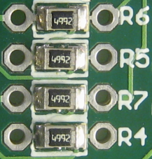 Photo 2.
Some actual values for R3_S and R2_S (see the table under the schematic in the calculator's page
to determine which is which).
When I encountered the original Chronulator and the meter which is the star of the section above, I decided to write a custom calculator to get at the resistor values to use to drive it. Then, when I modified the design I added additional sections to the calculator to handle circuit variations. The calculator uses a lot of PHP code that I have written over the last few years to do things such as work with engineering units, standard component values and generation of simple schematic images.
So. Select “Choronulator Current Source” from the menu at the left (you might want to open it in another tab or window so you can follow along here). From the drop-down box under “Choose desired calculation:” select “Suggest resistors to get a desired range: CronulatorSMD.” This puts the calculator in a mode where it tries to find values for R1, R2_T and R3_T which produce the desired full-scale current and meet the desired range of adjustment. Ignore the initial values shown in the schematic at the right; they are just defaults. The values of R2_S and R3_S, however, should be checked against those on your board. Photo 2 shows a situation where the resistors are 49.9 kΩ instead. (If you don't know how to read these codes, just substitute the last digit, a 2 in this case, with that many zeroes. So these are all 49900 Ohms or 49.9 kΩ.) Enter the actual values for these two resistors into the calculator (their tolerance range will almost certainly be the 1% that is the default condition: if there are 4 digits in the code then that's the case, if three digits then they are 5% parts).
Table 1 shows some sample calculations, all based on the 100 µA meter available from ShareBrained. Revised, 12-Jan-2010, for a more realistic Vbe value of 0.59 V.
| Meter | Desired range |
Target R tol. | > | R1 (the trimpot) |
R2_T | R3_T | Nominal range |
Worst-case range |
|---|---|---|---|---|---|---|---|---|
| 100 µA | ±20% | 1% | > | 5 kΩ | 4.99 kΩ | 7.68 kΩ |
74.9...122 µA or -25%…+22% |
77.3...120 µA |
| 100 µA | ±10% | 1% | > | 2 kΩ | 5.49 kΩ | 9.76 kΩ |
85...111 µA or -15.5%…+11.9% |
87...110 µA |
| 100 µA | ±5% | 1% | > | 2 kΩ | 5.76 kΩ | 2.32 kΩ |
89...107 µA or -11%…+6.1% |
90.7...106 µA |
| 100 µA | ±2% | 1% | > | 1 kΩ | 6.04 kΩ | 6.04 kΩ |
92...102 µA or -8%…+2.7% |
93.5...101 µA |
| Meter | Desired range |
Target R tol. | > | R1 (the trimpot) |
R2_T | R3_T | Nominal range |
Worst-case range |
| 100 µA | ±20% | 5% | > | 5 kΩ | 4.7 kΩ | 11 kΩ |
73.7...128 µA or -26.3%…+28.9% |
78.5...123 µA |
| 100 µA | ±10% | 5% | > | 2 kΩ | 5.1 kΩ | 680 kΩ |
84.6...119 µA or -15.4%…+19.6% |
90.1...114 µA |
| 100 µA | ±5% | 5% | > | 2 kΩ | 5.6 kΩ | 3.3 kΩ |
88.6...109 µA or -11.4%…+9.9% |
93.5...105 µA |
| 100 µA | ±2% | 5% | > | 1 kΩ | 5.6 kΩ | 160 kΩ |
92.1...109 µA or -7.9%…+9.9% |
97.4...105 µA |
| Suggested application cases | R1 (the trimpot) |
R2_T | R3_T | Nominal range |
Worst-case range | |||
| Probably the best for most cases: | 2 kΩ | 5.1 kΩ, 5% | Open |
84.5...119 µA or -15.5%…+14% |
90.0...114 µA | |||
| Tighter adjustment range, probably the best obtainable with 5% parts: | 2 kΩ | 5.6 kΩ, 5% | 3.3 kΩ, 5% |
88.6...109 µA or -11.4%…+9.9% |
93.5...105 µA | |||
| Next value down from the 5.1 kΩ | 2 kΩ | 4.7 kΩ, 5% | Open |
89.0...128 µA or -11%…+28% |
94.9...123 µA | |||
The range of values applicable to the 100 µA meters are those highlighted with the red background. Further refinement is shown in the third section, where the affects of some changes are shown.
A few observations:
- the program usually (perhaps always) produces a wider adjustment range than requested;
- even if you ask for a 2% range you wont get anywhere like it;
- if you expect to use 5% values for the added resistors you won't get any better than about ± 8 or 9% range.
Now that you have the suggested values you may want to adjust things. The main reason to do this is that you may have a good selection of resistors on hand but not the ones called up. To adjust the values click on the “click here” in the last bullet in the solutions box. Then you can substitute values and/or change the tolerance for the parts.
If you are experienced enough to want to remove the default SMD resistors and either put in a new 0805 resistor (if you are experienced, you should know what those numbers mean!) or just a single 1/8 W through-hole part, then there is a way to calculate a single resistor. To do this enter a value greater than 22E6 into either or both of the R2_S and R3_S value boxes in the “suggest” mode. The resultant values of R2_T and R3_T, from whichever tolerance range(s) that you specify, will work as a single value for R2 and R3.
Step 3: putting in the resistors...
 Photo 3.
It is quite OK to use a larger size than the 1/8 W. Here a 1 kΩ, 1/4 W, 5%
resistor is bent up to be put in as an R4_T.
R4, R5, R6 and R7 are composed of two resistances, one high value mounted as a surface mount component, and one through-hole normally in parallel with the first. R4 and R7 control the range of the minutes current source and R4 and R5 do the same for the hours circuit.
First you need to obtain the needed parts. The sites are designed for the smaller 1/8 W size resistors, however 1/4 W size parts can be used, they just won't look as great! Now, a point: what I mean by “1/8 W” and “1/4 W” isn't what the manufacturers call them. The size wanted here is something less than about 3.5 mm: these may be sold as 1/6, 1/8 or even 1/4 W these days. What I call a 1/4 W is a part that is typically about 6 or 7 mm long. The holes for the leads are 5 mm apart, but a longer part can have its leads bent “under then down” as shown in Photo 3.
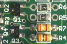 Photo 4.
A pair of resistors installed.
I have seen 1/8 W resistor assortments of 50 pieces of 50 values for as low as $10 plus
shipping from ebay sellers in Hong Kong such as this store  In this case the
assortments offered are just the 5% values (even though one of the sets is said to be made up of
1% parts, it does not list proper 1%, E96 values). I am not endorsing this store, just showing it as
an example.
Now solder in the chosen resistors. There's been lots of soldering tutorial activity on the web
in the last few years, or you may want to read the soldering section of the
original Chronulator manual (see page 8 of the pdf)  so I'm not going to go into that here.
Photo 4 shows two 5% 1/8 W resistors installed (in parallel with the 49.9 kΩ resistors that were already there) in the minutes circuit of a ChronulatorSMD.
Step 4: and the trim pots...
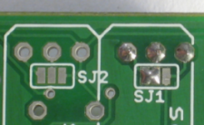 Photo 5.
A view from the bottom showing a trim pot soldered in for the minutes circuit only.
The trimpots P1 and P2 allow adjustability in the current sources so that the full scale current can be calibrated when the circuit is first turned on.
If the trimpots need to be soldered in as well, or changed then this section will inform you how to set up the pots. There is a 2-way “solder blob jumper” on the bottom of the board for each trimpot: if no solder blob bridges one of the two gaps then the trim pot will NOT affect the current setting. Photo 5 shows these.
To determine how to wire the solder blobs we need to identify the pins on the trim pots. Look at
Photo 6. Here we see both package variations for the Bourns 3362 parts  that the board is designed for (the
M—side-adjust and U—top-adjust versions on the data sheet). The thing to look for is pin
1 on either type. The photo makes this very clear.
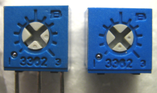 Photo 6.
The two trim-pot types. Note the metallic dot at the lower left corner of each type which
corresponds to the pin 1 identification molded in the plastic.
All you have to do is ensure that the side of the solder blob jumper that is nearest pin 1 is the side that gets the blob. (If you forget to put a blob in you will get the minimum current, if you get the blob on the wrong side, the current will increase with CCW not CW rotation of the control, but if you get a blob on both sides you will get the maximum current regardless of the pot's setting, so potentially your meter could be hurt. So it is best to inspect your soldering carefully after applying solder here to ensure that both sides are not shorted to the center.)
If you want to put the trim pots on the “bottom” of the board, make sure to jumper the appropriate side of the solder-blob jumpers before soldering on the trim pots.
A small point. If you want to make it easier to remove the trim pots in the future, then it is possible to solder only two pins instead of all three. You may omit soldering the pin nearest the side of the solder-blob jumper that has the solder blob. In Photo 5, above that would have been the terminal on the left.
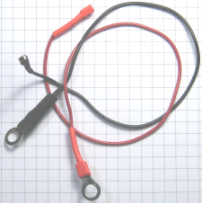 Photo 7.
A good hook-up is a neat one. Here are two wires that have square post receptacles and
ring-tongue terminals soldered on then covered with heat-shrink tubing.
Step 5: hooking up your meters...
The meters are meant to connect to the header at JP1, which is normally supplied with the board or already soldered onto the board. Note that a 4-way connector can be rotated without damaging meters—as long as they have the same full-scale currents.
The neatest method is to make up a little cable or pair of cables that use either a pair of 2-way or a single 4-way segment of female header connectors. The terminals of meters are often fairly large diameter screw terminals, and wires are often attached by winding them around the posts and clamping them between two washers, however ring-tongue terminals, either crimped or soldered, are the neatest way to go. See the BoM page for some suggestions. Photo 7 shows a simple pair of wires with the preferred type of connectors.
Of course, you can always just solder wires to the board, its up to you. (And a nice property of current sources is that short circuits don't hurt anything!)
3. Meter scales.
This can be the trickiest part for some people. It involves carefully removinging the meters' front covers and scale plates, then attaching some artwork over the existing scales then putting it all back together without touching a meter's pointer, at least not very much! Fortunately the instructions in the original Chronulator manual (see the link in step 3, above) cover these operations well.
4. Some other options..
There are a few other points which might be important to some users:
- SJ5, which is manufactured with a short circuit across it, enables the serial port. If lowest battery drain/longest life is desired then this track should be cut with a sharp knife to disable the serial I/O. The serial functions can always be re-enabled by applying a solder blob at the same point.
- If you are wanting to use the serial port, then, as in the original Chronulator, an FTDI FT232-based USB to serial device can be hooked up. The header (JP2) is wired exactly the same as the serial connection on the original board, and, since power will likely be coming from the USB connection, any battery or other power source should be removed. The boards are not normally supplied with JP2 installed.
- SJ3 (hours) and SJ4 (minutes) output solder-blob jumpers are designed with an initial short
which enables the normal current source outputs. If either or both of these are to be used
as direct outputs from the processor instead, then the manufactured shorts should be
cleared with a knife, and the other side of the 2-way jumpers should be shorted so that the
processor pins (PD3 and PB3 respectively) are connected to the pins of JP1 directly. (See the
layout page
 for jumper locations.)
